How to Test a PT100 RTD With a Multimeter
Oct 29, 2026Updated October 29, 2026. Reviewed by the Focusens Engineering Team.
| Probe temperature | PT100 | PT1000 |
|---|---|---|
| 0 °C (ice water) | 100.00 Ω | 1000.00 Ω |
| 20 °C | 107.79 Ω | 1077.94 Ω |
| 22 °C | 108.57 Ω | 1085.70 Ω |
| 25 °C | 109.73 Ω | 1097.35 Ω |
| 30 °C | 111.67 Ω | 1116.73 Ω |
| 100 °C | 138.51 Ω | 1385.06 Ω |
Values from the IEC 60751 equation. Full tables: PT100 resistance table and PT1000 resistance table.
A good PT100 reads the table value for the temperature it is actually at, within its class tolerance; the "100" in its name applies only at 0 °C. At room temperature that means somewhere between about 107.8 and 111.7 Ω, and the exact figure depends on the room. A reading of 109 Ω means 23.1 °C, 110 Ω means 25.7 °C and 112 Ω means 30.8 °C (our calculation), so a bench check needs a thermometer beside the probe or an ice bath. The thermometer's own error counts too: ±0.5 °C is ±0.19 Ω on a PT100 (our calculation). Let the probe lie untouched beside it until both readings stop moving.
The class tolerance in ohms is small. IEC 60751 sets Class A at ±(0.15 + 0.002|t|) °C and Class B at ±(0.3 + 0.005|t|) °C, the same in °C for any nominal resistance:
| Class | At 0 °C | PT100 window at 0 °C | At 20 °C | PT100 window at 20 °C |
|---|---|---|---|---|
| A | ±0.15 °C | 99.94 to 100.06 Ω | ±0.19 °C | 107.72 to 107.87 Ω |
| B | ±0.30 °C | 99.88 to 100.12 Ω | ±0.40 °C | 107.64 to 107.95 Ω |
Our calculation from the IEC 60751 Table 2 formulas and the slope at each temperature. A PT1000 window is ten times wider in ohms and the same in °C.
A PT100 changes about 0.39 Ω per °C, so 1 Ω of error is about 2.6 °C. That one number explains most of what follows: a tenth of an ohm in the test leads, a corroded terminal or a cheap meter all show up as degrees.
Testing an RTD with a two-probe multimeter means measuring the element plus some lead resistance and then taking the leads out by arithmetic. The order below works for PT100 and PT1000 probes.
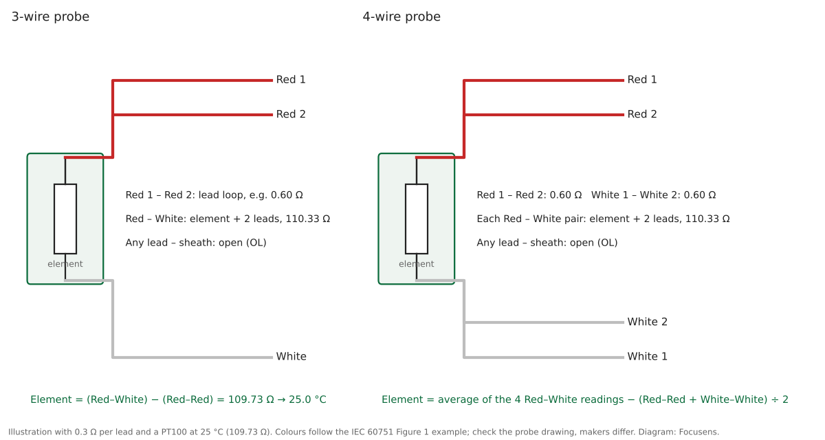
A worked example with 0.3 Ω per lead and a PT100 at 25 °C: red to red reads 0.60 Ω, red to white reads 110.33 Ω, and the element is 110.33 − 0.60 = 109.73 Ω, which is 25.0 °C. Uncorrected, the same reading would say 26.5 °C (our calculation). The subtraction assumes the leads are equal, which is also what a 3-wire input assumes.
On a 4-wire probe, measure all four red–white pairs and both same-end pairs. Element = average of the four red–white readings − (red–red + white–white) ÷ 2. That is exact for any combination of lead and terminal resistances. Taking one red–white reading minus (red–red + white–white) ÷ 2 instead assumes equal leads: with one red leg 0.15 Ω high, it reads 0.19 °C high if that pair includes the high leg and 0.19 °C low if it does not, at 25 °C (our calculation). A two-probe multimeter cannot use the 4-wire principle itself: across any red–white pair it always sees two leads in series with the element. The BIPM guide explains that in a true 4-wire measurement "there is no current flowing through the voltage leads", which a two-terminal meter cannot arrange (BIPM guide to IPRTs).
Lead colours help but do not prove anything. IEC 60751 Figure 1 shows red–red–white for 3-wire and red–red–white–white for 4-wire as an example, and other makers use other schemes. Our RTD wiring guide covers the colour codes and terminal mapping; the meter readings above decide which lead is which.
A handheld multimeter proves that a PT100 is open, shorted, leaking or far off its table value; it cannot prove that the probe is still within Class A or Class B. The meter's own resistance uncertainty, converted to °C on a PT100 at 20 °C, is larger than the Class A tolerance on every meter below:
| Meter and range | Resistance spec | On a PT100 at 20 °C |
|---|---|---|
| Fluke 114 to 117, 600.0 Ω | ±(0.9 % + 2) | ±1.17 Ω = ±3.0 °C |
| Fluke 83V, 600.0 Ω | ±(0.4 % + 2) | ±0.63 Ω = ±1.6 °C |
| Fluke 87V, 600.0 Ω | ±(0.2 % + 2) | ±0.42 Ω = ±1.1 °C |
| Keysight U1251B, 500.00 Ω | ±(0.08 % + 10) | ±0.19 Ω = ±0.48 °C |
| Keysight U1252B / U1253B, 500.00 Ω | ±(0.05 % + 10) | ±0.15 Ω = ±0.40 °C |
| For comparison: Class A / Class B | ±0.19 °C / ±0.40 °C |
Specs from the Fluke 114 to 117 and Fluke 83V/87V data sheets (distributor copies) and the Keysight U1250 series data sheet. The Keysight figures apply after NULL and the 83V/87V 600 Ω figures after REL; the 114 to 117 data sheet attaches no such condition, so subtract the shorted-lead reading by hand on those meters. Conversion to °C is our calculation.
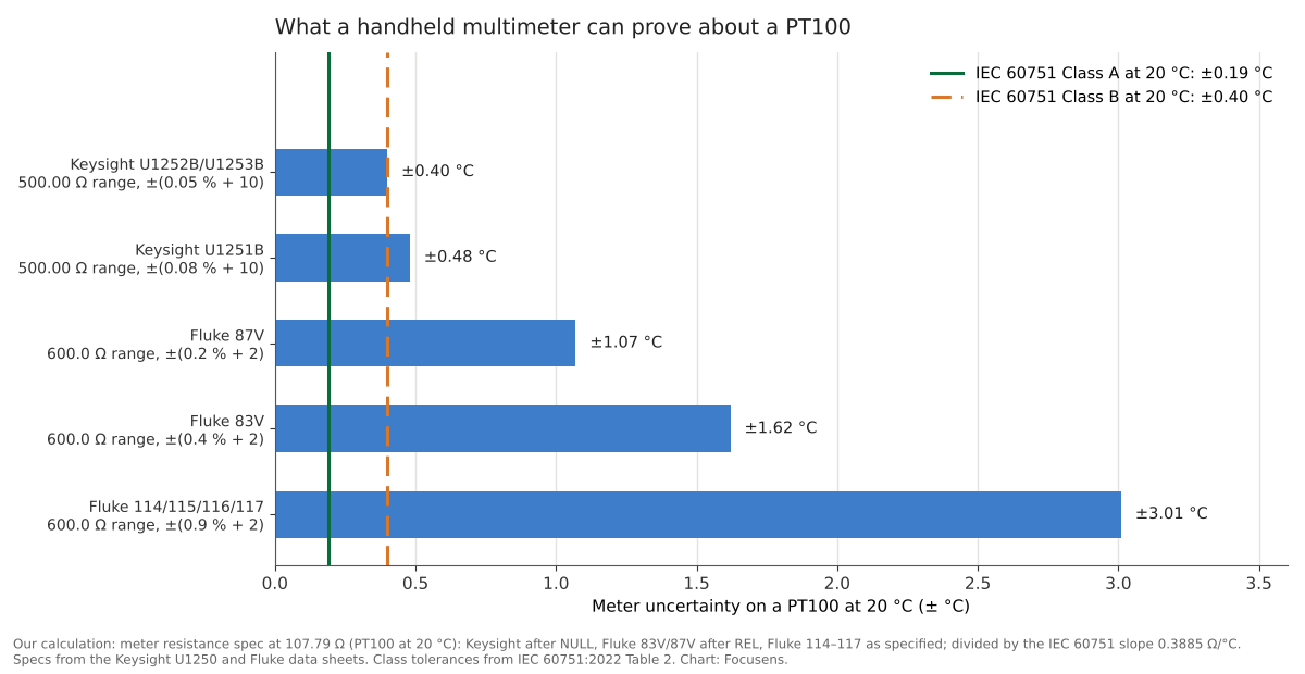
An electrician's meter is therefore a fault finder, not a calibration tool. A reading 3 °C off the table on a ±(0.9 % + 2) meter says nothing about the sensor; a reading 15 °C off, or an open circuit, does. To check the class you need a reference thermometer and a bath, or a laboratory calibration.
A PT1000 is not finer per digit on the same meter: one count on a 6,000-count meter is about 0.26 °C on both, because the PT1000 also needs a range ten times larger. Where the PT1000 is easier is contact and test-lead resistance, the same reason it tolerates long 2-wire cables (see PT100 vs PT1000). An un-nulled 0.3 Ω adds 0.77 °C to a PT100 reading and only 0.077 °C to a PT1000 (our calculation).
The meter's own test current does not heat the element much. Keysight lists 1.04 mA on its 500 Ω range, which is about 0.12 mW in a PT100 at 20 °C; with the self-heating that Endress+Hauser gives for a 6 mm thin-film insert in water, 310 mK/mW, that is about 0.04 °C (E+H TS111, our calculation). On a bench the probe is in air, where BIPM says self-heating "may be as much as a few tenths of a degree" for 100 Ω sensors at up to 1 mA; that is still smaller than most handheld meters' own uncertainty.
Every RTD fault leaves a pattern in the ohms readings, and the direction of the error points to the cause. Extra series resistance reads hot on a 2-wire probe; leakage between the conductors, through damp insulation or through the sheath, reads cold.
| What the meter shows | Likely cause | Effect on the temperature reading |
|---|---|---|
| OL across the element | Broken element or lead | Sensor-failure alarm; the output goes high or low depending on the input's failure-mode setting |
| Near 0 Ω across the element | Short between the conductors | Sensor-failure alarm, or reads below range |
| Table value plus a few ohms, 2-wire | Corroded terminal, bad crimp, long thin cable | Reads hot: +1 Ω = +2.6 °C on a PT100 |
| The two red–white readings differ by more than a few tenths of an ohm (3-wire) | Loose or oxidised terminal on one of the same-end leads | Reads cold if it is the lead the input subtracts; almost no error if it is the sense lead |
| Both red–white readings high by the same amount, red–red normal (3-wire) | Extra resistance in the single lead or its terminal, or the element is simply warmer than your reference | Reads hot: +1 Ω = +2.6 °C on a PT100; if the excess disappears at the head, it is in the cable or terminals |
| Below the table value, and a finite reading to the sheath | Moisture in the insulation, damaged cable | Reads cold, and ten times worse on a PT1000 |
| Reading drifts while you watch | Probe warmed by your hand or not yet at room temperature; a loose terminal or broken strand; moisture in the insulation | Settles if it is temperature; jumps when you move the cable if it is a connection; keeps wandering otherwise |
Directions for series resistance, 3-wire imbalance and leakage from the BIPM guide to IPRTs (sections 4.4 and 4.5); what an input does on an open or short depends on its failure-mode setting. Magnitudes are our calculation.
The 3-wire case catches people out. The BIPM guide gives the residual error of a 3-wire connection as the difference between two lead resistances divided by the sensor slope, and says the circuit "still requires the three lead resistances to be equal". In that equation, R_meas = R(t) + R_L1 − R_L2, R_L1 is the lead alone at one end of the element and R_L2 the compensating lead at the other end; the third lead carries no measuring current. On a red–red–white probe the white lead is R_L1. One extra ohm in the white lead reads about 2.6 °C hot, the same ohm in the compensating red lead about 2.6 °C cold, and in the other red lead it does almost nothing (our calculation at 20 °C). The lead arithmetic is in our page on RTD lead resistance error. Emerson's transmitter manual puts it the same way: "a 3-wire sensor will not fully cancel lead resistance error because it cannot compensate for imbalances in resistance between the lead wires" (Rosemount 644 manual). A corroded terminal can therefore make a 3-wire RTD read low, not only high.
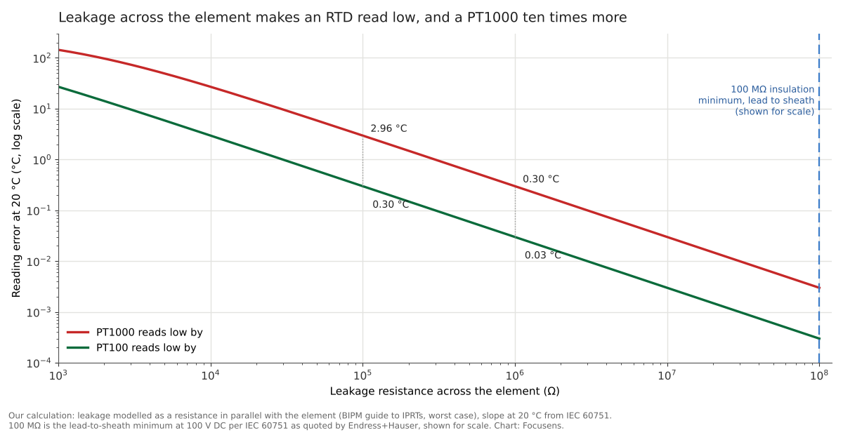
Leakage reads low because it acts as a resistor in parallel with the element. BIPM: "the effect of poor insulation is to decrease the measured resistance, and the effect increases with the ratio of R(t) / Rins." A PT1000 has ten times the resistance, so the same leakage costs it ten times as many degrees:
| Leakage across the element | PT100 reads low by | PT1000 reads low by |
|---|---|---|
| 100 MΩ | 0.000 °C | 0.003 °C |
| 1 MΩ | 0.03 °C | 0.30 °C |
| 100 kΩ | 0.30 °C | 2.96 °C |
| 10 kΩ | 2.96 °C | 26.9 °C |
Our calculation at 20 °C, worst case with the leakage across the whole element. A lead-to-sheath reading is only a proxy: it shows the leaks at the two ends of the element in parallel. If they are equal, the path through the sheath shunts the element with four times the reading, which quarters these errors; a leak at one end only does not shunt the element at all. Leakage straight between the conductors, which BIPM says is most common in long PVC-insulated cables, does not show on a sheath test; compare the panel and head readings instead.
Test lead-to-sheath insulation with an insulation tester at 100 V DC, with all leads tied together and the transmitter disconnected. Endress+Hauser quotes the IEC 60751 requirement for its inserts as "a minimum test voltage of 100 V DC: >100 MΩ at 25 °C" (E+H TS111). A handheld multimeter tests at a few volts: under 2.7 V open circuit on the Fluke 114 to 117 and under 7.3 V on the 83V/87V. Their top ohms ranges, 40 MΩ and 50 MΩ, stop short of 100 MΩ, so OL there proves more than 40 or 50 MΩ at a few volts, not 100 MΩ at 100 V DC.
More voltage is not better. The BIPM guide says moisture "can be detected by using a low voltage (< 100 V) insulation tester", and that "ideally the insulation resistance should exceed 100 MΩ, but moisture can cause it to be as low as a few kilo ohms". The two sources set opposite bounds: BIPM asks for a tester below 100 V to find moisture, and Endress+Hauser's 100 MΩ figure is for a minimum of 100 V DC. A 100 V setting sits on the boundary of both, so we suggest it unless the probe's data sheet names another voltage. Thin inserts are rated for less than an electrician's megger delivers: Endress+Hauser specifies dielectric strength of "≥ 250 V DC over 5 s" for its TS111 3 mm inserts other than QuickSens, so a 500 V or 1,000 V test can exceed the rating of a small probe. Never apply the test voltage to a transmitter still connected to the leads, and on an intrinsically safe or flameproof installation follow the site's permit procedure before connecting any tester.
Mineral-insulated probes stay dry only while their seal holds. BIPM explains that magnesia "has an affinity for water, so IPRT assemblies using magnesia must be hermetically sealed", notes that "most commonly, problems occur with long lengths of PVC insulated cable", and reports that in one study of 94 industrial sensors, "Moisture (69 % of the cases) rather than strain (19 % of the cases) was believed to account for most of the drift". In one operator's account, three RTDs read about 111 °C instead of about 117 °C after a heat-exchanger change. Replies suggested thermowell air gaps, insertion depth and stem heat loss, and wet magnesia as one possible cause; no test result was posted. If moisture were the cause, the 2.27 Ω drop would need about 9 kΩ of leakage across a PT100 (our calculation), a level BIPM says wet insulation can reach. Three probes shifting by the same amount point first to the installation; a lead-to-sheath insulation test separates the two.
An ice-water check gives one exact reference point, 0 °C, where a PT100 should read 100.00 Ω and a PT1000 1000.0 Ω. NIST's procedure: shave clean ice to 2 to 5 mm, pack it in a flask with distilled water, wait 15 to 30 minutes, and use the bath when "no ice is floating in the flask, and there is no excess water on the surface of the ice" (NIST SP 819). Wait until the reading has stopped changing for a minute; a probe in a thermowell can take two minutes to reach 90 % of a step even in flowing water, according to Endress+Hauser's TR10 data.
The pass window has to include the meter as well as the class:
| Probe and meter | Accept at 0 °C |
|---|---|
| PT100 Class A, Keysight U1251B | 100 ± 0.24 Ω (±0.61 °C) |
| PT100 Class B, Keysight U1251B | 100 ± 0.30 Ω (±0.76 °C) |
| PT100 Class A, Fluke 87V | 100 ± 0.46 Ω (±1.17 °C) |
| PT100 Class B, Fluke 114 to 117 | 100 ± 1.22 Ω (±3.1 °C) |
| PT1000 Class A, Keysight U1251B | 1000 ± 1.9 Ω (±0.48 °C) |
Our calculation: class tolerance at 0 °C plus the meter's resistance spec at 100 Ω or 1000 Ω.
A reading outside these windows in a proper ice bath is a real fault. A reading inside them still does not prove the class, for the reasons in the meter table above.
When the probe passes its ohms checks and the display is still wrong, substitute a fixed resistor at the input. A probe maker's manual describes the method: "When checking a transmitter decade resistor should be connected with 3-wire line to the input terminals", set to the start and end of the range, and the outputs "should be 4 mA and 20 mA accordingly" (ALF Sensor manual). On a 3-wire input, connect one end of the resistor to the single-lead terminal and the other end to both same-end terminals with a short link; on a 4-wire input, link each pair.
| Simulated temperature | PT100 resistor | PT1000 resistor | 4–20 mA on a 0–100 °C span |
|---|---|---|---|
| 0 °C | 100.00 Ω | 1000.0 Ω | 4 mA |
| 50 °C | 119.40 Ω | 1194.0 Ω | 12 mA |
| 100 °C | 138.51 Ω | 1385.1 Ω | 20 mA |
Our calculation from the IEC 60751 equation.
Use a 0.1 % resistor or a decade box. A resistor's tolerance is a percentage of its value, so its error in degrees grows along the table: a ±1 % resistor is ±2.6 °C at the 0 °C value, ±3.1 °C at 50 °C and ±3.7 °C at 100 °C, and a ±0.1 % resistor ±0.26, ±0.31 and ±0.37 °C, the same on PT100 and PT1000 inputs (our calculation). If the input reads the resistor correctly, the fault is in the probe or the field cable; if it reads the resistor wrong, the fault is in the input, its configuration or the wiring at the terminals.
Two more checks split the problem quickly. Swap two probes between channels: if the fault stays with the channel, the probe is not the cause. And look at what the probe sees: if both probes read 116 Ω at rest, they are at about 41 °C (106 °F), whatever the screen shows. A reading that wanders with a fixed resistor connected points to interference or to the input, not to the probe. In one operator's account of an unstable cold-room RTD, the readings were steady while the evaporator was off and the RTD cable shared a tray with the motor power cable; no resistor test or fix was reported.
Focusens builds PT100 and PT1000 probes in 2-wire and 3-wire versions, and in 4-wire on our PT100/PT1000 3-wire or 4-wire probe, to Class B ±(0.3 + 0.005|t|), or to Class A ±(0.15 + 0.002|t|) in 3-wire or 4-wire only and within the temperature range IEC 60751 allows for Class A; the standard says thermometers better than Class B "shall have 3-wire or 4-wire configuration with 4-wire configuration being recommended". Our PT100 platinum RTD probe page lists insulation resistance of "DC500V min.100Mohm" and a hi-pot test of 1250 V at 1 mA for one minute, with 2000 V and 3000 V options; see also the waterproof PT100 probe and the RTD sensor range. A field insulation test at 100 V DC is well inside that rating.
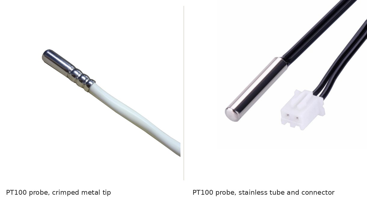
For a replacement, send us the element (PT100 or PT1000), class, number of wires, temperature range, cable length and a photo of the old probe and its label. The NTC and thermocouple versions of this test are in our guides to testing an NTC thermistor and testing a thermocouple.
A PT100 is 100.00 Ω at 0 °C. It rises about 0.39 Ω per °C, so it reads 107.79 Ω at 20 °C, 109.73 Ω at 25 °C and 138.51 Ω at 100 °C on the IEC 60751 curve. A PT1000 reads ten times those values.
Disconnect the RTD, null the meter leads and measure across the element on a low ohms range. On a 3-wire RTD, subtract the reading between the two same-end leads. Compare the result with the table at the probe's temperature, then check each lead to the sheath for an open reading.
A PT100 is bad if it reads open (OL), near 0 Ω, far from the table value for its temperature, or anything other than open from a lead to the sheath. A reading a few ohms high on a 2-wire probe usually means a bad connection rather than a bad element.
Measure all four red–white pairs, then the red pair and the white pair. The element is the average of the four red–white readings minus half the sum of the two pair readings. A two-probe meter always includes two leads in each red–white reading.
A handheld multimeter cannot tell Class A from Class B. Class A allows ±0.19 °C at 20 °C, while typical handheld meters are ±0.4 to ±3 °C on a PT100 (our calculation from their data sheets). Checking the class needs a reference thermometer and a stable bath.
A PT100 reading 110 Ω is at about 25.7 °C, which is a normal room temperature. If the room is cooler, an un-nulled test lead or a 2-wire cable can add the difference: 0.3 Ω reads about 0.8 °C warm.
A PT1000 is easier to check for lead and contact resistance, which cost it a tenth as many degrees. It is more affected by moisture: the same leakage pulls a PT1000 reading ten times as far down, although the insulation test is the same for both. On the same meter, one digit is worth about the same in °C on both.
Drafted with AI assistance from the standards and data sheets linked above; the Focusens Engineering Team checked the figures against those sources and our product pages on October 29, 2026. Resistance values and classes come from IEC 60751:2022, lead and leakage effects from the BIPM guide, insulation figures from Endress+Hauser, meter specifications from Keysight and Fluke, and the ice bath from NIST. Figures marked "our calculation" are computed from those sources; none is a bench measurement on a Focusens part.
No.1 XiSan Road, Electromechanical Industry Park , High&New Tech.Zone. Hefei,Anhui,China
tel : +86-551-69109668
Whatsapp : +86-13339100504
e-mail : info@focusens.com
Skype : melodyliu520






 +86-551-69109668