Motor Insulation Class B F and H Temperature Limits and PTC Rating
Nov 11, 2026Updated November 11, 2026.
| Insulation class | Hot-spot limit | Average rise at 40 °C ambient (resistance method) |
|---|---|---|
| B (130) | 130 °C (266 °F) | 80 K |
| F (155) | 155 °C (311 °F) | 105 K |
| H (180) | 180 °C (356 °F) | 125 K |
Limits and rises from the WEG motor manual (document 11171349, revision 18, section 4.5.1.1, Table 4.4), which applies IEC 60034-1. °F values are our conversion. The 140 °C sensor is our calculation, shown in the PTC section below.
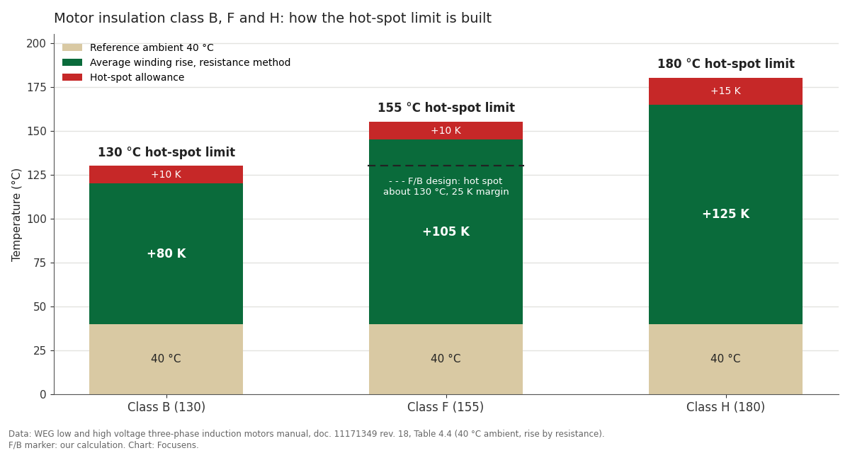
Each insulation class limit is the sum of three numbers: a 40 °C reference ambient, the average winding rise the standard allows, and a hot-spot allowance for the part of the winding that runs hotter than the average. The resistance method measures that average, because it reads the whole winding's change in resistance, so the allowance covers what the measurement cannot see.
| Insulation class (IEC thermal class) | Reference ambient | Average rise, resistance method | Hot-spot allowance | Hot-spot limit |
|---|---|---|---|---|
| B (130) | 40 °C | 80 K | 10 K | 130 °C |
| F (155) | 40 °C | 105 K | 10 K | 155 °C |
| H (180) | 40 °C | 125 K | 15 K | 180 °C |
From WEG's motor manual, Table 4.4 "Insulation class", document 11171349 revision 18 (August 2026).
IEC 60034-1 sets the rise limits in clause 8.10. In the 2022 edition (edition 14) they sit in Table 8, "Limits of temperature rise of windings indirectly cooled by air", with separate rows for different machine sizes. The current edition 15 replaced it in March 2026, and its published list of technical changes names updated values for thermal class 200 (N) but not for B, F or H.
NEMA MG 1 sets the same 80, 105 and 125 K for a standard motor but moves the limit with service factor and enclosure. NEMA's own comparison of NEMA and IEC practice gives these limits for low-voltage random-wound motors, by resistance, at 40 °C:
| NEMA MG 1 motor type | Class B | Class F | Class H |
|---|---|---|---|
| 1.0 service factor (other than the rows below) | 80 K | 105 K | 125 K |
| 1.15 service factor or higher | 90 K | 115 K | not listed |
| Totally enclosed non-ventilated, 1.0 service factor | 85 K | 110 K | 130 K |
| Encapsulated windings, 1.0 service factor | 85 K | 110 K | not listed |
Source: NEMA vs. IEC Motor Standards, NEMA, rise-by-resistance table for low-voltage random-wound motors. The same document notes that IEC does not recognise service factor.
The resistance figure and an embedded detector's reading are not interchangeable. IEC 60034-1 treats the measuring methods separately in clause 8.5. When you compare a motor against its class, check which method its test report used before you subtract anything.
A motor rated class F insulation with class B rise uses insulation good for 155 °C but is designed to the 80 K class B rise, so at rated load in 40 °C air its hot spot sits near 130 °C, 25 K under the insulation limit (our calculation from WEG's Table 4.4). The shorthand for this design is F/B.
| Design (insulation / rise) | Hot spot at rated load, 40 °C ambient | Margin to insulation limit |
|---|---|---|
| B / B | 130 °C | 0 K |
| F / B | 130 °C | 25 K |
| F / F | 155 °C | 0 K |
| H / B | 130 °C | 50 K |
| H / F | 155 °C | 25 K |
| H / H | 180 °C | 0 K |
Our calculation: 40 °C + the rise class's average rise + its hot-spot allowance, against the insulation class limit, all from WEG Table 4.4.
What the margin is worth comes from the ageing rule that insulation life halves for every 10 K of extra temperature. The TU Darmstadt machine-design notes give it as 50 % per 10 K for solid insulation (Montsinger's rule, derived from Arrhenius). Read backwards, 25 K below the limit is about 2^2.5, or 5.7 times the thermal life at the limit (our calculation). The notes describe it as a statistical rule over many insulation samples, so use 5.7 as an order of magnitude for comparing designs, not as a life prediction for one motor.
Engineers who specify these motors describe the margin in similar terms. In a June 2024 Eng-Tips thread on F/B construction, one contributor estimated that class F insulation run at class B temperatures lasts roughly five times longer, and another said many users order F/B simply to add thermal margin. On a 2007 CR4 thread about trip settings, an engineer from Kolkata wrote that his specifications call for class F insulation with the rise held to class B, so that a hot restart or an overload has room. Those are users' estimates, not measurements; the factor of five sits close to the 5.7 from the 10 K rule.
Service factor spends part of that margin. Under NEMA MG 1 a motor with a 1.15 service factor may rise 90 K instead of 80 K at service-factor load (NEMA), so an F/B motor run at its service factor reaches about 140 °C at the hot spot and keeps 15 K of its 25 K (our calculation). IEC motors carry no service factor, so the margin on an IEC F/B nameplate is the full 25 K at rated output.
Between class B and class F, the difference is the margin: at the same rise class F gives 25 K more room, and at the full class F rise it gives none. Class H adds another 25 K on top of F, and an H/F motor has the same margin as an F/B motor at a higher operating temperature. Compare motors by the margin column.
A motor winding built to its full class rise reaches the class limit at its hot spot under exactly the conditions the rating assumes: air at 40 °C or cooler, an altitude of 1000 m (3300 ft) or lower, rated load and working cooling. Hotter or thinner air, overload or poor cooling push it past the limit. NEMA's comparison gives the same 40 °C and 1000 m for both NEMA and IEC motors before any compensation is needed (NEMA). Above either figure the permitted rise comes down; IEC 60034-1 tabulates the adjustment (Table 10 in the 2022 edition), and WEG's manual treats anything above 40 °C as a special condition that the motor's own documentation has to cover.
Cooling can fail while the motor current stays normal. WEG's manual warns that obstructed air inlets and outlets "could cause overheating". A current-based overload relay misses this case, because it infers winding temperature from current. A sensor embedded in the winding reads the winding itself; our PTC motor thermistor guide covers that wiring.
Drive-fed motors at low speed are where users report this most often. A maintenance worker on r/PLC in October 2025 described cooling-unit motors (3/4 hp, 460 V, three on one drive) whose windings shorted while the drive's minimum speed was below 30 Hz. By the poster's account the failures stopped once the minimum was raised to 30 Hz, and setting one unit back to 20 Hz cost a motor within a month. The most upvoted reply blamed the shaft fan moving too little air near 20 Hz, while another blamed voltage peaks from long, unequal cables, so the thread does not settle the cause. On a 2009 CR4 thread, a power engineer made the general point: a drive's thermal model does not account for the lost fan cooling at low speed, which is why winding thermistors are there as the backup.
A hand on the housing or an infrared reading of the frame says little about the winding hot spot, which sits inside the slots and end windings where the class limit applies. Where a motor has measuring sensors, WEG's manual says alarm and trip temperatures "must be set at the lowest possible value", suggests an alarm about 10 °C above the machine's operating temperature at full load, and caps both at the values in the motor's wiring diagram. Set protection from what the motor actually runs at, with the class limit as the ceiling.
A PTC thermistor's rated temperature (TNAT) has to sit inside a window: high enough that the sensors stay below their switching band at full load, and low enough that one overheated winding trips the relay before the insulation limit. For rated temperatures of 90 to 160 °C, the DIN VDE V 0898-1-401 limits published in TDK's B59100 motor-protection data sheet allow up to 550 Ω at TNAT − 5 K and require at least 1330 Ω at TNAT + 5 K and 4 kΩ at TNAT + 15 K. Thermistor relays trip between 2.7 and 3.85 kΩ on the four makers' data compared in our PTC motor thermistor guide, so a string of three sensors is guaranteed to trip by TNAT + 5 K when all three windings overheat together, and only by TNAT + 15 K when one winding runs hot on its own.
That gives two edges for the window:
| Motor design (insulation / rise) | Full-load hot spot at 40 °C | TNAT window, one hot winding | Standard rated points that fit | Window if only an even overload must trip |
|---|---|---|---|---|
| B / B | 130 °C | none (135 to 115 °C) | none | none (135 to 125 °C) |
| F / B | 130 °C | 135 to 140 °C | 140 °C | 140, 145, 150 °C |
| F / F | 155 °C | none (160 to 140 °C) | none | none (160 to 150 °C) |
| H / B | 130 °C | 135 to 165 °C | 140, 145, 150, 155, 160 °C | same |
| H / F | 155 °C | 160 to 165 °C | 160 °C | 160 °C |
| H / H | 180 °C | none (185 to 165 °C) | none | none |
Our calculation. Hot spot = 40 °C + the rise class's average rise + its hot-spot allowance (WEG Table 4.4). Sensor limits and the list of standard rated points (60 to 180 °C) from TDK B59100, September 2020; only the 90 to 160 °C points use the limits above. TDK's 170 and 180 °C types switch over a ±7 K band and guarantee 10 kΩ only at TNAT + 23 K, so check their data sheet before using them on a class H motor.
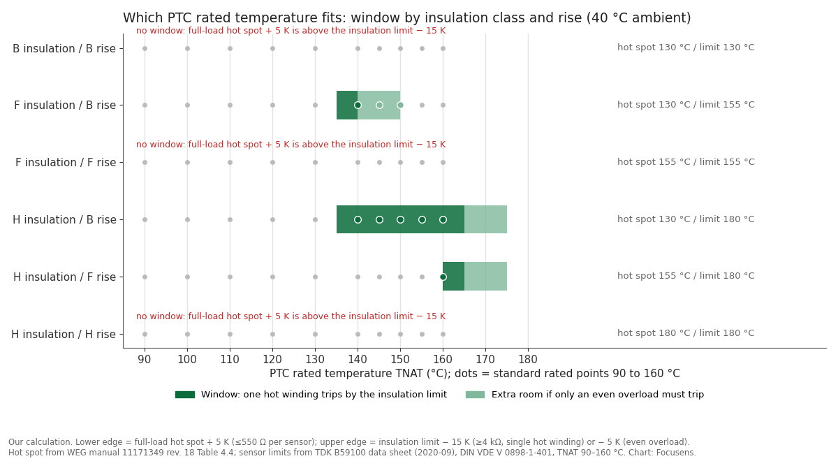
Three rows have no window, and they show the main limit of PTC protection. A motor that uses its full class rise at rated load in 40 °C air has no rated temperature that does both jobs: any sensor that stays quiet at full load is only guaranteed to trip above the insulation limit. The 25 K margin of an F/B or H/F design is what makes room for a PTC.
Forum answers to the same question spread widely. When a user on a 2007 CR4 thread asked what trip temperature suits a class F motor, replies ranged from 120 °C (to hold the winding to class B), through about 145 °C (the class F limit less 10 K for the hot spot), to 165 °C for a 1.0 service-factor motor. The last figure is above the 155 °C class F limit, and none of the replies asked what rise the motor was built to, which is what moves the window in the table. In an Eng-Tips thread on a burned-out motor, the poster said the only protection was an embedded thermostat he believed tripped at 190 °C, a figure he later traced to an unreadable copy of MG 1; two replies said it should have been set to 140 °C. That agrees with the F/B row, but the thread does not give the motor's rise, so it cannot confirm it.
The window opens when the real figures are lower than the worst case, and it closes when they are higher. At 30 °C ambient an F/B motor's full-load hot spot is about 120 °C, so 130 °C sensors also fit. A class F motor whose heat-run test shows a 90 K average rise has a hot spot near 140 °C, and no standard point meets the one-hot-winding edge. The same happens to a NEMA F/B motor run continuously at its 1.15 service factor: its hot spot is also near 140 °C, so it loses the 140 °C point, and 145 or 150 °C sensors cover only an even overload (all three our calculation). Where you have the motor's test report, use its measured rise instead of the class figure, and keep the sensor where it reads the end winding rather than the frame.
The relay side fails in its own ways, according to users. A refinery operator on CR4 in 2009 reported a motor thermistor rated to about 3 kΩ at most, wired to a drive input that needed 4.7 kΩ to trip; a reply pointed out that motors normally carry three sensors meant to be wired in series, and that a single sensor may never trip. Under the DIN limits above, one sensor is only guaranteed 4 kΩ at TNAT + 15 K, so a 4.7 kΩ input has no guaranteed trip point for a single sensor within those limits (our reading of the TDK data sheet). The opposite case came from a control.com thread: one of about two dozen PTC-protected motors tripped on a shorted-thermistor fault, and the user reported about 175 Ω cold on that motor against 245 Ω on a healthy one. Short-circuit thresholds differ by relay make (one reply quoted under 20 Ω for one family), so check the relay's data sheet before condemning the sensor.
Each rated temperature has its own lead colour, listed in our DIN 44081 and DIN 44082 guide. For a class F motor built to a class B rise, specify 140 °C sensors. For a motor that runs at its full class rise, a PTC alone cannot protect the insulation limit with margin, so add a measuring sensor such as a PT100 and set its alarm and trip from the full-load temperature, as WEG's manual describes.
Eight facts about the motor decide the PTC rated temperature, and most of them are on the nameplate or in the test report. Collect them before you order sensors, and before a rewind, because a rewinder who fits a different TNAT changes the protection without changing anything you can see.
| Check | Why it moves the rated temperature | Where to find it |
|---|---|---|
| Insulation class | Sets the hot-spot limit: 130, 155 or 180 °C | Nameplate |
| Rise class, or the measured rise at rated load | Sets the full-load hot spot, the lower edge of the window | Nameplate; heat-run test report |
| Service factor | A 1.15 service factor allows 10 K more rise under NEMA MG 1 | Nameplate (NEMA motors) |
| Maximum ambient and altitude | The rating assumes 40 °C and 1000 m; above that the rise limit comes down | Data sheet; order specification |
| Speed range on a drive | A self-ventilated motor loses cooling at low frequency | Drive parameters; motor maker's derating curve |
| Sensor position | End winding reads close to the hot spot; the frame lags | Rewind specification |
| Relay or drive input | Its trip value and cold-string limit set how many sensors fit in series | Relay data sheet; see our PTC motor thermistor guide |
| Lead colour of the sensors fitted now | Identifies the TNAT already in the motor | Motor terminal box; DIN 44082 colour table |
Rewinds and starter changes are where users report protection quietly disappearing. The owner of a small injection-moulding company wrote on Eng-Tips that his rewound motor smoked within about five minutes, and that the shop later said it had forgotten to refit the thermistor. On a 2017 CR4 thread, a user reporting for a plant described a new 18.5 kW motor whose embedded sensors were never connected to a relay because the starter had no input for them; it failed within eight months, with the insulation damage at the sensor locations. On Mike Holt's forum, a moderator who works as an electrical engineer advised that where a soft starter has no thermistor input, a separate thermistor trip relay has to be wired into the start/stop circuit. After any rewind or starter change, confirm the sensors are fitted, wired and read by something that can stop the motor.
After a replacement, test the string the way the PTC thermistor multimeter test describes, with an ohms range and never an insulation tester across the sensor pair. To get a proposal for a specific motor, send us the nameplate photo, the relay or drive model and the answers in the table.
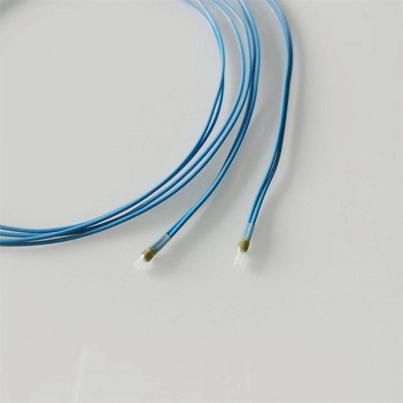
Focus Sensing and Control (Focusens) makes MZ6 PTC thermistors for motor windings: an MZ6 mini version for motor windings and an MZ6 triple PTC thermistor for motor protection, with the wider range under thermistors and sensors for motors.
Focusens is certified to ISO 9001:2015 by NOA, valid to 30 March 2029, and to IATF 16949:2016 by AENOR, certificate RA02-0749/2025, valid to 13 September 2028; both certificates are shown on our certifications page.
Ask for the current MZ6 data sheet for the rated temperature you choose, and check its resistance limits against the window in the table above before you approve a sample.
IEC thermal classes run 90 (Y), 105 (A), 120 (E), 130 (B), 155 (F), 180 (H), 200 (N), 220 (R) and 250 °C, and NEMA's motor tables give rise limits for classes A, B, F and H (NEMA). The motor rise tables in this guide cover B, F and H.
Class F insulation has a hot-spot limit of 155 °C. At a 40 °C ambient that allows a 105 K average rise by resistance plus a 10 K hot-spot allowance (WEG Table 4.4); NEMA MG 1 allows 115 K on a motor with a 1.15 service factor.
Class B temperature rise is an 80 K average winding rise over a 40 °C ambient, measured by resistance, which with a 10 K hot-spot allowance reaches the 130 °C class B limit. NEMA MG 1 allows 90 K at a 1.15 service factor and 85 K on a totally enclosed non-ventilated motor.
Class F insulation tolerates 25 K more than class B. At the same class B rise, an F/B motor runs 25 K below its insulation limit, about 5.7 times the thermal life by the 10 K rule (our calculation); at the full class F rise it has no more margin than a B/B motor.
Class H insulation is rated to 180 °C against 155 °C for class F. It adds margin only if the motor's rise stays lower than class H allows: an H/F motor keeps 25 K, an H/H motor none.
The insulation class sets the upper edge of the PTC window and the rise sets the lower edge. On a class F motor built to a class B rise, at 40 °C ambient, that window holds one standard rated point: 140 °C (our calculation from WEG and TDK data).
No.1 XiSan Road, Electromechanical Industry Park , High&New Tech.Zone. Hefei,Anhui,China
tel : +86-551-69109668
Whatsapp : +86-13339100504
e-mail : info@focusens.com
Skype : melodyliu520






 +86-551-69109668